Tips for Examining Rolling Element Bearings: Prepping for a Root Cause Analysis (RCA)
Abstract. In our last series highlighting the 4 primary Failure Modes (FM) of component failures (erosion, corrosion, fatigue and overload), we discussed how to read fractured surfaces. In this follow up series, we will take a look at tips on how to collect, preserve and examine such failed components.
I will reiterate my intent to make this series, as with the others, as basic and generic as possible. This will be old news, and metallurgy 101, to seasoned analysts. However, my outreach is to those on the front lines. You are the ones ones who will determine if the analysts get these failed parts or not, for a detailed root cause analysis. How the parts are preserved is extremely important to the investigators.
I will try to provide you enough education to make it challenging and fun, not only to properly preserve the failed parts, but to participate with your curiosity as to what influences, adversely impacted the failed parts?
Some of the basics in evidence preservation after a failure, include the following:
- Secure the failure scene. Rope off (caution tape) the scene and ensure it is safe for investigators to enter
- Take many pictures from many angles. This will preserve the scene in its ‘as-is’ state. Remember, at this point you may not know what is relevant to the failure itself, so ensure you take pictures of the entire failure scene. As you collect the facts and analyze them, things in your initial pictures will make more sense.
- Clear close-ups of failed areas. Take high resolution pictures of the failure scene and especially the failed surfaces of broken components. These pictures will likely be blown up to look for more granularity. Such pictures will include the following (in this article) but are certainly not limited to them:
- Sight glasses – ensure you take pictures at the angles in which someone would be viewing the sight glass (sometimes sight glasses can be easily mis-read due to parallax error [the angle at which they are viewed])
- Piping – note if the failures occur at ‘T’s’, ‘U’s’ or straight runs. If cracks, are they parallel or perpendicular to the pipe run? Is the failure at a weld?
- Valve positions – note valve positions as on, off or partial open
- Structure – base etc. – note any anomalies in structures which could contribute to the failure (i.e. – resonance, soft foot, etc.)
- Couplings – note all anomalies on the coupling (just like we will described here for roller bearings)
- Guards – note the condition and location of guards (even if they exist at all).
4. Take pictures up & down stream of failure. Initially, we may not know if there were upstream and/or downstream influences that contributed to the failure. Therefore we must preserve those scenes as well.
5. Take video of failure event area. Chances are you will be time-pressured by production to hurry up and get what you need and then get out, as they will want to get production rolling again. Fastest way to preserve the scene is with video!
6. Map out the event scene as needed. Once you have your pictures and videos, draw a map or sketch of the failure scene and note where the anomalies are the located. This will be a team job aide in the investigation.
7. Interview key people who were present as the event unfolded. It is extremely important to interview witnesses immediately. The longer you wait to interview, the more attention to detail you will lose (due to short-term memory loss). You will also lose direct observation information if the witness is influenced by talking to others involved (say in the break room), and their opinions are reshaped as a result.
8. Map out where each person was during the event. Just like we talked about mapping out physical anomalies at the failure scene, we should also note where key players were as the failure unfolded (as opposed to where they should have been).
9. Create a timeline. An accurate and detailed timeline of events leading up to the failure is always critical to the investigation.
10. Leave instructions with area leadership about what parts you want & where to stage them. You may not be able to get certain parts you need because they are still in operation. If this happens, you will need to get cooperation of area leadership to ensure you get the parts when they are available (perhaps a shutdown). This will require some planning about where you want them to stage the desired parts.
In the following clips, you will notice there is some redundancy in the guidance on each clip. This is because it is anticipated that if this article is printed off, each clip will stand independent of the others.
Since this article is focusing only on rolling element bearings, we will breakdown the components of a roller bearing and provide basic guidance of how to preserve, document and examine the evidence.
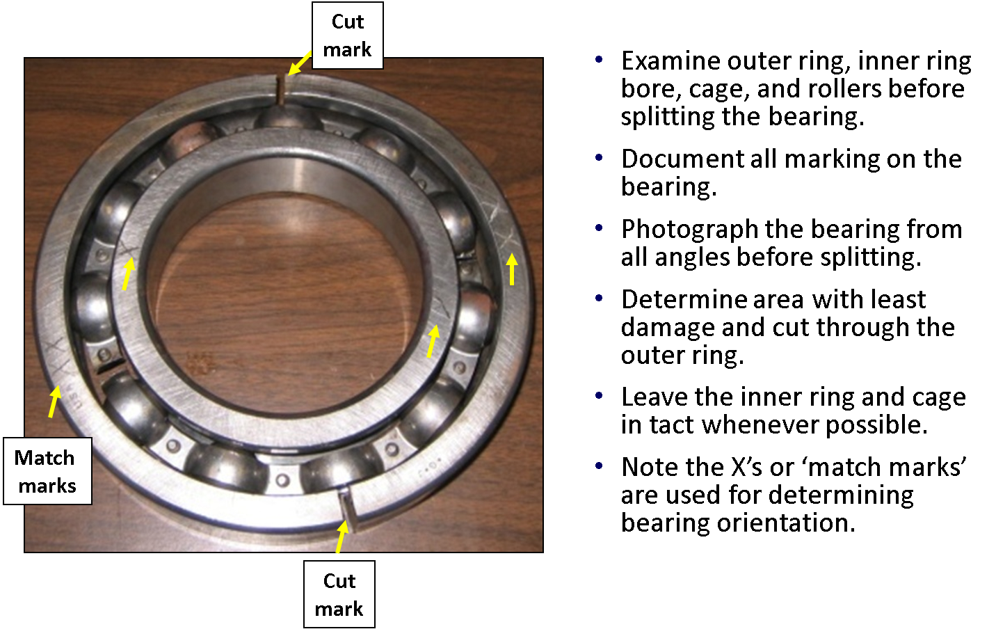
Let’s start with the failed roller bearing when it is still intact, at least when it is still in one piece.
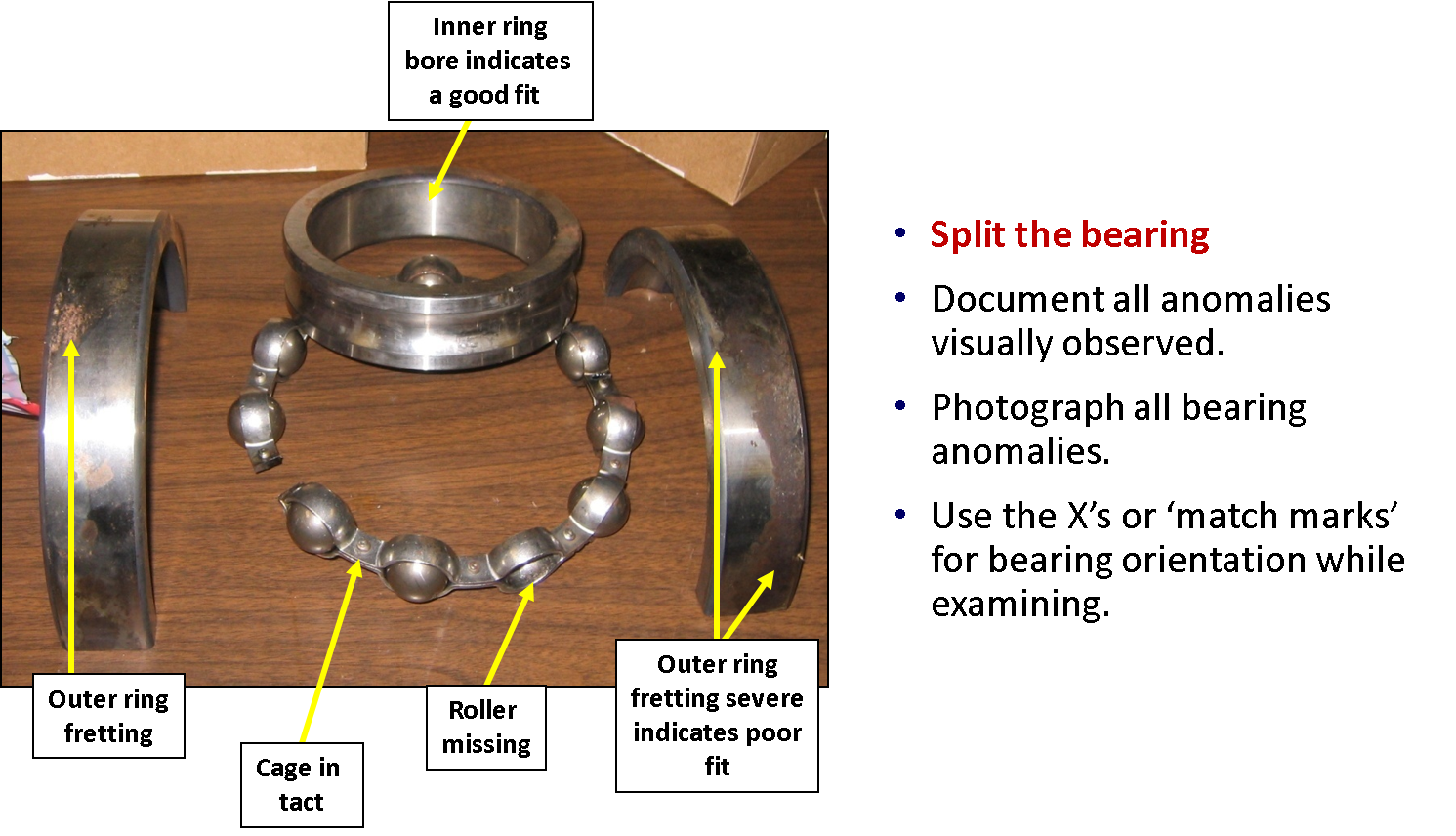
Once we have the bearing properly split, we will then layout the components of the bearing on a clean surface so we can begin to document and further photograph the bearing internals.
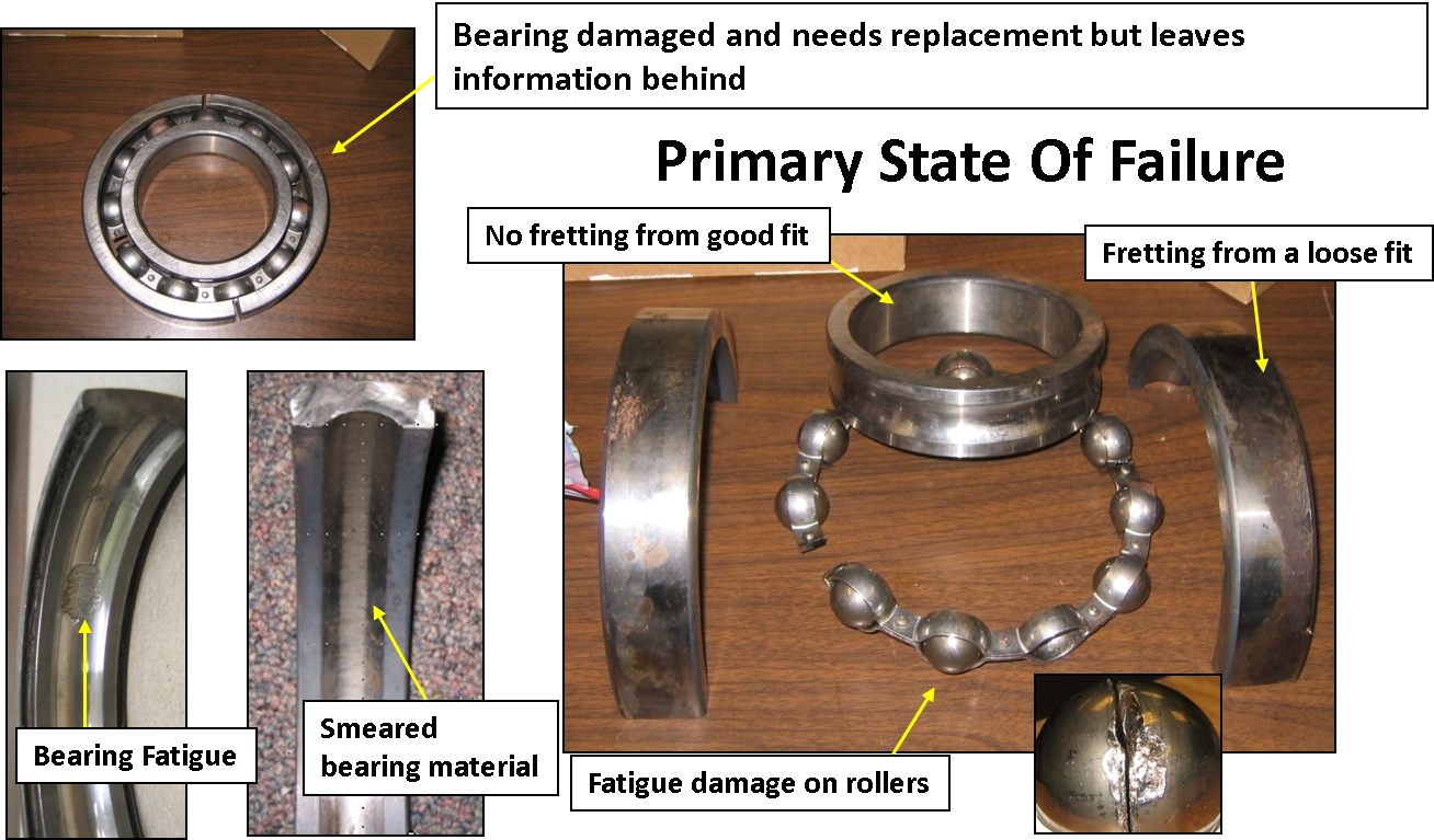
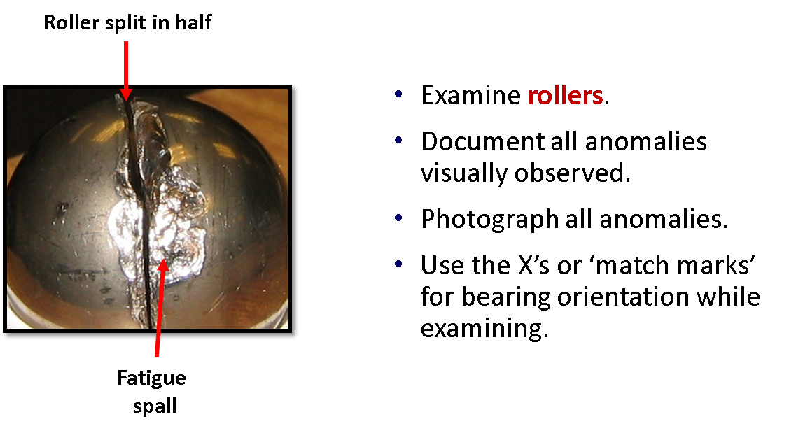
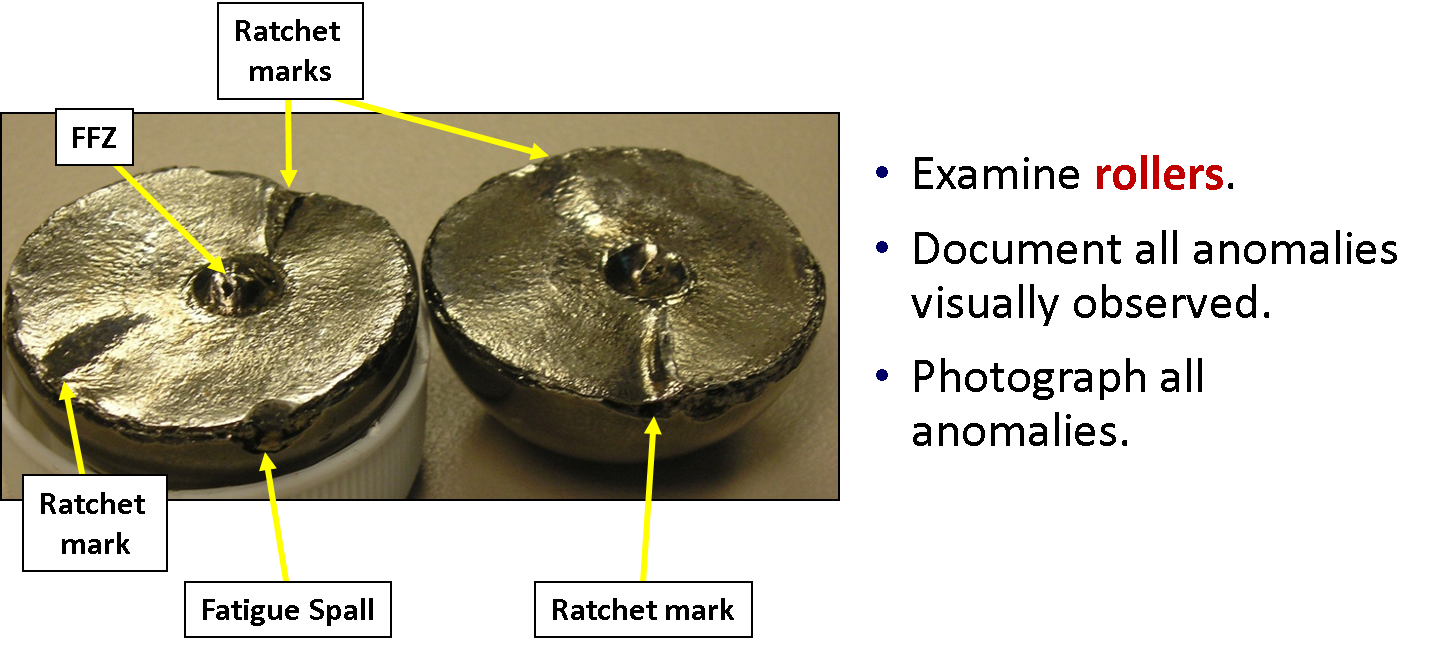
When examining the rollers themselves, we need to take the high res pictures and note the anomalies as expressed in the example below.
Based on the above picture, after being split, we then expose the failure patterns of the failed surface (as we described in the previous articles on the recognizing erosion, corrosion, fatigue and overload)
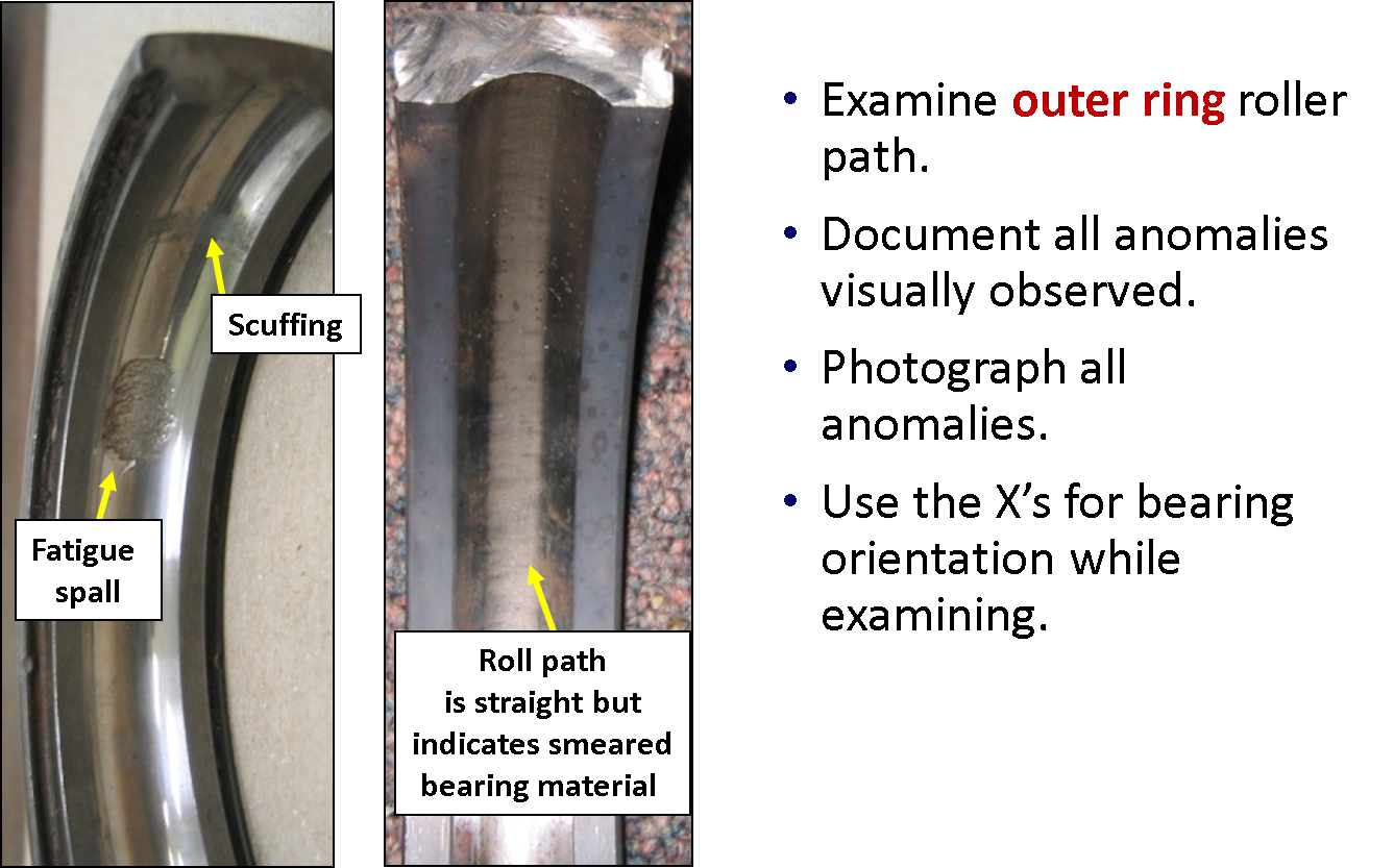
Turning to examination of the outer ring, same as described before. Take hi res pics and note anomalies to be explained.
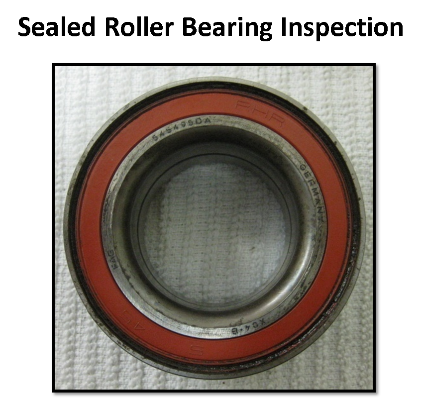
Now let’s move on to look at sealed roller bearings, which will essentially follow the same paths from a failure preservation, documentation and examination standpoint.
On the sealed roller bearing, we will examine the outer ring, take hi res pics and note anomalies as in the example below.
Looking at the inner ring bore, the routine is the same. In the example below we see evidence of fretting indicating a problem with proper fit.
Continuing on with looking at the inner ring bore, we note anomalies on the inside and the outside of the ring. In this case we have fretting on the inside and spalling on the outside of the ring.
This is just another example of the examination and notation of anomalies. The inner ring looks fine indicating proper fit, but there is scuffing on the ball path indicating secondary damage that needs to be explained.
Let’s move on to the roller bearing cage. Same routine for examination with regards to pics and notations. Here we show pics of both sides and note a lubrication related anomaly that has to be explained (How Could? per our Root Cause Analysis approach discussed in prior articles).
We move on to the rollers, taking pics from various sides. In the examples below we note the anomaly that the rollers were not moving freely and there is evidence of excessive heat. All of these conditions have to explained as to how they came to be (cause-and-effect), via an effective RCA.
This will end our basic tips on how to preserve, document and examine roller bearings. I will post similar articles in the future, but on different components. However, the handling of them will all mirror what I described in this article.
Just as an FYI, I am pulling all of this material from public workshops we offer. These workshops range from the very basic to those who really want to get into this fascinating field of metallurgical analysis and root cause analysis and become Lead Investigators.
PROACT Lead Investigator Training – https://reliability.com/lead-investigator.html (2 weeks)
PROACT RCA Methodology Training – https://reliability.com/root-cause-analysis-training.html (3 Days)
PROACT Investigation Management System, Software Solutions – https://reliability.com/software.html (Desktop, Enterprise and Online)
As always, I appreciate all of the great feedback and the sharing from the veterans in the field…the front-lines who make things happen!! Thank you for your time and participation.
About the Author
Robert (Bob) J. Latino is former CEO of Reliability Center, Inc. a company that helps teams and companies do RCAs with excellence. Bob has been facilitating RCA and FMEA analyses with his clientele around the world for over 35 years and has taught over 10,000 students in the PROACT® methodology.
Bob is co-author of numerous articles and has led seminars and workshops on FMEA, Opportunity Analysis and RCA, as well as co-designer of the award winning PROACT® Investigation Management Software solution. He has authored or co-authored six (6) books related to RCA and Reliability in both manufacturing and in healthcare and is a frequent speaker on the topic at domestic and international trade conferences.
Bob has applied the PROACT® methodology to a diverse set of problems and industries, including a published paper in the field of Counter Terrorism entitled, “The Application of PROACT® RCA to Terrorism/Counter Terrorism Related Events.”
Recent Posts
How to Improve Your RCA Program: A Practical Guide for Reliability Leaders
The 2026 Reliability Cost Curve: How World-Class Teams Bend It Downward
The Reliability Leader’s 2026 RCA Playbook: A Straightforward Guide to Starting the Year Strong
Why You Never Have Time for Root Cause Analysis (And How World-Class Teams Fix It)
Root Cause Analysis Software
Our RCA software mobilizes your team to complete standardized RCA’s while giving you the enterprise-wide data you need to increase asset performance and keep your team safe.
Root Cause Analysis Training


